Sunday, 26 August 2018

Clap On Clap Off Relay

  1. Components

Condenser Mic
555 Timer IC
Transistor BC547
Resistors (1k, 47k, 100k ohm)
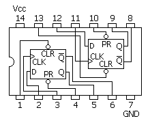
IC7474 [ DM74S74N (D-type flip-flop) ]

Capacitors(22nf,10uf) 

I have reduced  the complexity of the circuit and made it simpler 

A "Clap On Clap Off" switch is an interesting concept that could be used in home automation. It works as a switch which makes devices On and Off by making a clap sound. Although its name is “Clap switch”, but it can be turned ON by any sound of about same pitch of Clap sound. The main component of the circuit is the Electric Condenser Mic, which has been used as a sound sensor. Condenser Mic basically converts sound energy into electrical energy, that in turns used to trigger 555 timer IC, through a Transistor and triggering of IC 555 timer  works as a Clock pulse for D-type flip-flop and would turn ON the Relay, which will remain ON until the next clock pulse means until the next Clap/sound. So this is the Clap Switch which will turn ON with first Clap and turn OFF with the second Clap. If we remove the D-type Flip flop from the circuit, the will not be turned OFF automatically. For better understanding, I recommend studying the previous circuit before studying this one. 


Here we are using Electric Condenser Mic for sensing the sound and converting it into electric signal, transistor to trigger the 555 timer IC, 555 IC to SET & RESET the D-type flip-flop and     D-type flip-flop to remember the logic level (Relay ON or OFF) until next Clap/sound.
Here we are using 555 timer IC in Monostable Mode, whose output can be obtained at PIN 3 

Working of D Flip Flop


Here we are using Positive Edge Triggered D-type flip-flopwhich means this flip flop only responds when clock pulse would go from LOW to HIGH. The Flip-flop remembers the previous output i.e. High or Low until the next clock pulse.


We have used IC DM74S74N of 7474 series. IC DM74S74N is the Dual D-type Flip-flop IC, in which there are two D-type Flip-flops, which can be either used individually or as a master-slave toggle combination. We are using one D-type Flip-flop in our circuit. Pins for first D flip-flop are the left side and for second flip flop are at right side. Also there are PRE and CLR pins for both the D-type Flip-flops which are active-low pins. These pins used to SET or RESET the D-type Flip-flop respectively, regardless of Input and Clock. We have connected both Vcc and ground to make the IC active.


NOTE:- 

  1. This circuit works with any 7474 series.

Friday, 24 August 2018

Clap Based Relay Control

Components

Electric Condenser Mic
555 Timer IC
Transistor BC547
Resistors (220, 1k, 47k, 100k ohm)
Relay and Battery (9v)

Clap switch is an interesting hobby circuit which turns on the lights with a clap sound. Although its name is “Clap switch”, but it can be turned ON by any sound that is approximately the same pitch of Clap sound.

The main component of this clap switch circuit is the Electric Condenser Mic, which has been used as a sound sensor. Condenser Mic basically converts sound energy into electrical energy, that in turns used to trigger 555 timer IC, through a Transistor and triggering of 555 IC would turn ON the Relay. I have made this circuit as simple as possible. you can find many complex Clap switches (using 555 IC) with some more components in it, and merely doing the same thing. Even make things simpler require more effort than making it complex.


Clap Based Relay

You can see the circuits and connections in the above schematic diagram of clap switch. Initially, the transistor is in OFF state because there is not enough base-emitter voltage to turn it ON and the point near the collector is at a high potential, and the point is connected to Trigger pin 2 of 555 IC, as a result, Trigger pin 2 is also at high potential. As we know that, to trigger the 555 IC through Trigger PIN 2, the voltage of the PIN 2 must be below Vcc/3. So at this stage Relay is not excited.

Now when we produce some sound near the condenser mic, this sound will be converted into electrical energy and it will raise the potential at the Base, which will turn the Transistor ON. As soon as the transistor becomes ON, the potential at the Point would become low and it will trigger the 555 IC because of the low voltage (below Vcc/3) at Trigger Pin 2 and Relay will get excited. We have connected the Relay to Output PIN 3 of 555 IC.


TEST:-


To test this circuit you need to clap loudly as this small condenser mic don’t have long range. Or you can directly hit at the mic lightly.

In this circuit the relay is always in ON State, but what if we also want to control the switching OFF of the Relay? Means if we want to turn ON the Relay with a clap/sound and turn OFF it with second sound/clap? We can do this by using D-flipflop/IC 7474, I will show you this in my next circuit.