Monday, 3 February 2020

Water Filled Headphones - INMERGO

Water rather than air carries sound in designer Rocco Giovannoni's Inmergo headphones, which promise rich audio even for people who are hard of hearing.

A 2019 graduate of the Royal College of Art's MA in Design Products, Giovannoni designed the soft silicone headphones to improve upon current bone-conduction audio technology.


Like other bone-conduction headphones on the market, his design  bypasses the eardrum and conveys sound as vibrations through the bones of the skull, directly to the cochlea — the "hearing" part of the inner ear.
Unlike any other device on the market, it does so via waterproof speakers that are fully immersed in liquid and then sealed in a pliable membrane. This membrane sits against a person's skin, transmitting sound vibrations through touch.

While existing bone-conduction headphones have proved popular among people who are deaf or have some hearing loss — as well as cyclists who want to listen to music but remain aware of their surroundings — the devices are hampered by poor sound-quality.
"I believe these are wasting an opportunity for a technology that has the potential of improving the music quality of common earphones and headphones," said Giovannoni.
"Inmergo aims to unravel the undiscovered potential of bone conduction by delivering innovative and inclusive sound experiences that can improve the quality of our life."


                                                                                                                                                                                                                                                                                                                                                                                                                                                                                                                                                                                                                                                                                                                                                               Inmergo does not quite match the sound experience of traditional headphones; instead, it offers a high-fidelity audio experience that's all of its own.
Giovannoni describes it as "immersive omnidirectional" sound with richer bass. "It feels like you're inside the song," says one wide-eyed subject in Inmergo's user testing video.
Another tester, a deaf person with a unilateral cochlear implant, described it as one of the best listening experiences of her life.

Inmergo is a novel patent-pending audio technology availing of bone conduction through liquid and gels as sound media. It generates an omnidirectional surround effect and gives richness and vibrotactile feedback to the low-end enhancing a more immersive perception of sound. By bypassing the outer and middle ear, it is inclusive to people with hearing loss and cochlear implants
Click here to visit official Link


Sunday, 2 February 2020

Sound Reactive LED and LED STRIP

Hi friends in this article you can learn about how to make a sound reactive LED or sound reactive LED strip. Here the LED turns ON and OFF with respect to the beats of the music.These lights glow according to the length and pitch  of music beats, basically these are designed to pick the high intensity sound like Bass sound. So here you can learn how to synchronize lights with music.

Components Required

  • Condenser Mic
  • 2- NPN Transistor BC547
  • Resistors- 10k (2),  1M (1), 1K(if using LED)
  • Ceramic Capacitor 100nF
  • 1 LED or LED Strip
  • 9v Battery
  • Breadboard and connecting wires

Working of Circuit

For LED


In this Simple LED Music Light Circuit, condenser mic picks up the sound signals and converts them into voltage levels. These voltage signals are further fed into R-C filter or HIGH PASS filter , to eliminate the noise from the sound. Further a NPN transistor ( BC547) is used to amplify the signals, from the High Pass filter. Then finally these music signals are given to the transistor. Transistor in this works as amplifier, and glows the  LEDs according to the sound pattern. This generates a very interesting sequence of dancing LEDs which follows the beats as per their intensity or pitch. We can also add more LEDs with transistor to make it cooler.


We can adjust the sensitivity of MIC by changing the value of 100nf and 1M, by using the formula for R-C filter:

 F = 1/ (2πRC)

F is the cut off frequency, means filter only allow frequency above than F. It can be easily deduced that more the value of RC, less the cut off frequency and higher the sensitivity of MIC. And higher the sensitive of circuit means MIC can pick low volume sounds, hence LEDs can glow on low pitch music also. So by adjusting its sensitivity we can make it less sensitive to reacts only on high note beats or we can also make it more sensitive to react on every little beat in the music. Here we have set its sensitivity at moderate level.

Condenser Mic should be connected properly in the circuit, according to its polarity. To determine the polarity of MIC one should look at mic terminals, the terminal which have three soldering lines, is the negative terminal.

Transistor BC547 is a NPN transistor, which is used as a Amplifier here. NPN transistor acts as a open switch when there is no voltage applied on its Base (B) and it acts as closed switch when these is some voltage at its base. Generally 0.7 volt is enough to get it fully conducted. 

For LED strip


The circuit is as similar as used for LED but the difference is that the change of LED into LED strip and removing the resistor and providing enough supply needed for led strip .

Monday, 29 July 2019

Bluetooth 5.0 Development Board Cypress CYW20819

The CYW20819 is a advanced Bluetooth 5.0 development board which can be programmed using Modus Toolbox. These Bluetooth 5.0 board have a very large operation range which is around  100 meters in indoor and 200 meters in outdoor, It made IoT possible in Bluetooth. This board has data transfer speed up to 3MBPS.


 Applications featuring Bluetooth connectivity are trending towards lower power,more application-level features, and smaller BoM cost and board space. The CYW20819 Bluetooth Wireless MCU enables you to meet all these critical requirements.

CYW20819 also supports value-add application features by having a powerful Arm Cortex-M4 CPU and a host of peripheral blocks like ADC, SPI, UART, and I2C that aid in interfacing with external on-board sensors. The presence of these peripheral blocks, on-chip flash memory, and integrated buck and LDO regulators also enables reduced BoM cost and PCB footprint. Cypress’s advanced CMOS manufacturing process and the support for various system power modes enable you to design battery-operated,low-power applications using CYW20819.The device is intended for use in audio(source), sensors (medical, home, security), HID and remote-control  functionality, as well as a host of other IoT applications.

The below figure is the block diagram of CYW  20819


Sunday, 26 August 2018

Clap On Clap Off Relay

  1. Components

Condenser Mic
555 Timer IC
Transistor BC547
Resistors (1k, 47k, 100k ohm)
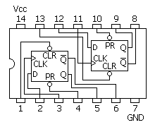
IC7474 [ DM74S74N (D-type flip-flop) ]

Capacitors(22nf,10uf) 

I have reduced  the complexity of the circuit and made it simpler 

A "Clap On Clap Off" switch is an interesting concept that could be used in home automation. It works as a switch which makes devices On and Off by making a clap sound. Although its name is “Clap switch”, but it can be turned ON by any sound of about same pitch of Clap sound. The main component of the circuit is the Electric Condenser Mic, which has been used as a sound sensor. Condenser Mic basically converts sound energy into electrical energy, that in turns used to trigger 555 timer IC, through a Transistor and triggering of IC 555 timer  works as a Clock pulse for D-type flip-flop and would turn ON the Relay, which will remain ON until the next clock pulse means until the next Clap/sound. So this is the Clap Switch which will turn ON with first Clap and turn OFF with the second Clap. If we remove the D-type Flip flop from the circuit, the will not be turned OFF automatically. For better understanding, I recommend studying the previous circuit before studying this one. 


Here we are using Electric Condenser Mic for sensing the sound and converting it into electric signal, transistor to trigger the 555 timer IC, 555 IC to SET & RESET the D-type flip-flop and     D-type flip-flop to remember the logic level (Relay ON or OFF) until next Clap/sound.
Here we are using 555 timer IC in Monostable Mode, whose output can be obtained at PIN 3 

Working of D Flip Flop


Here we are using Positive Edge Triggered D-type flip-flopwhich means this flip flop only responds when clock pulse would go from LOW to HIGH. The Flip-flop remembers the previous output i.e. High or Low until the next clock pulse.


We have used IC DM74S74N of 7474 series. IC DM74S74N is the Dual D-type Flip-flop IC, in which there are two D-type Flip-flops, which can be either used individually or as a master-slave toggle combination. We are using one D-type Flip-flop in our circuit. Pins for first D flip-flop are the left side and for second flip flop are at right side. Also there are PRE and CLR pins for both the D-type Flip-flops which are active-low pins. These pins used to SET or RESET the D-type Flip-flop respectively, regardless of Input and Clock. We have connected both Vcc and ground to make the IC active.


NOTE:- 

  1. This circuit works with any 7474 series.

Friday, 24 August 2018

Clap Based Relay Control

Components

Electric Condenser Mic
555 Timer IC
Transistor BC547
Resistors (220, 1k, 47k, 100k ohm)
Relay and Battery (9v)

Clap switch is an interesting hobby circuit which turns on the lights with a clap sound. Although its name is “Clap switch”, but it can be turned ON by any sound that is approximately the same pitch of Clap sound.

The main component of this clap switch circuit is the Electric Condenser Mic, which has been used as a sound sensor. Condenser Mic basically converts sound energy into electrical energy, that in turns used to trigger 555 timer IC, through a Transistor and triggering of 555 IC would turn ON the Relay. I have made this circuit as simple as possible. you can find many complex Clap switches (using 555 IC) with some more components in it, and merely doing the same thing. Even make things simpler require more effort than making it complex.


Clap Based Relay

You can see the circuits and connections in the above schematic diagram of clap switch. Initially, the transistor is in OFF state because there is not enough base-emitter voltage to turn it ON and the point near the collector is at a high potential, and the point is connected to Trigger pin 2 of 555 IC, as a result, Trigger pin 2 is also at high potential. As we know that, to trigger the 555 IC through Trigger PIN 2, the voltage of the PIN 2 must be below Vcc/3. So at this stage Relay is not excited.

Now when we produce some sound near the condenser mic, this sound will be converted into electrical energy and it will raise the potential at the Base, which will turn the Transistor ON. As soon as the transistor becomes ON, the potential at the Point would become low and it will trigger the 555 IC because of the low voltage (below Vcc/3) at Trigger Pin 2 and Relay will get excited. We have connected the Relay to Output PIN 3 of 555 IC.


TEST:-


To test this circuit you need to clap loudly as this small condenser mic don’t have long range. Or you can directly hit at the mic lightly.

In this circuit the relay is always in ON State, but what if we also want to control the switching OFF of the Relay? Means if we want to turn ON the Relay with a clap/sound and turn OFF it with second sound/clap? We can do this by using D-flipflop/IC 7474, I will show you this in my next circuit.

Monday, 2 July 2018

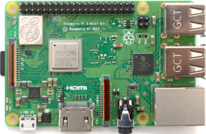
Introduction to Raspberry Pi


What is Raspberry Pi?
Raspberry Pi
Raspberry Pi Logo.svg
Raspberry Pi 3 B+ (39906369025).png
Raspberry Pi 3 Model B+
Release date14 March 2018; 3 months ago
Introductory priceUS$35
Operating system9front
Android Things
Arch Linux ARM
CentOS
Debian
Fedora
FreeBSD
Freedombox
Gentoo Linux
Kali Linux
Kano
NetBSD
OpenBSD
OpenWrt
Plan 9
Raspbian
RISC OS
Slackware
SUSE
Ubuntu Core
Ubuntu MATE
Windows 10 IoT Core
System-on-chip usedBroadcom BCM2837B0
CPU1.4 GHz 64/32-bit quad-core ARM Cortex-A53
Memory1 GB LPDDR2 RAM at 900 MHz
StorageMicroSDHC slot
GraphicsBroadcom VideoCore IV 300 MHz/400 MHz
Power1.5 W (average when idle) to 6.7 W (maximum under stress)


The Raspberry Pi is a series of small single-board computers developed in the United Kingdom by the Raspberry Pi Foundation to promote the teaching of basic computer science in schools and in developing countries.

Where Raspberry Pi can be used?
The Raspberry Pi has been used on land for robots, in the air for quadcopters, on the sea in racing yachts and drone boats, and there’s even a couple in space right now as well. The Raspberry Pi is conquering everywhere but under the waves, in the murky depths. Now, this is all set to change. Nowadays  Raspberry Pi is also used in Hacking.


"One of the main things I like about Raspberry Pi is its community"

What Languages does Raspberry Pi support? 
Can be programmed with a large number of programming languages. Python, C, C++, JAVA, Scratch, and Ruby all come pre-installed by default on the Raspberry Pi

OTHER LANGUAGES THAT CAN BE USED ARE:-

HTML

Javascript

Perl

Erlang